OWL: An object-oriented Framework for
intelligent Home and Office Applications
Bernd Brügge
Ralf Pfleghar
Thomas Reicher
Technische Universität
München
Lehrstuhl für angewandte Softwaretechnik
Arcisstraße 21
80333 München
Germany
Email: {bruegge,pfleghar,reicher}(at)in.tum.de
Abstract. The goal
of the OWL (Object-Oriented Workplace Laboratory) system
is to provide an object-oriented and component-based
framework that supports the engineering of applications
for the design, simulation, construction, and operation
of buildings with more efficient use of building
facilities. OWL is based on a software architecture using
a combination of web and object technology. It offers
location transparent and manufacturer independent access
to a variety of facility control systems, and allows
users to define "scenes" to adapt their work
environment.
In this paper, we describe the
requirements, system design and a conceptual prototype of
the OWL framework. We discuss how the application of
design patterns and component technology impacts the
framework to support the maintenance of corporate sites
globally distributed across the world. A conceptual
prototype of OWL written in Java is operational, managing
distributed facilities at the Intelligent Workplace at
Carnegie Mellon University and at the Technische
Universität München.
Keywords. intelligent
workplace, object-oriented workplace, control system,
facility management, design patterns, framework,
component-based software engineering
|
Introduction
The
health, well-being, motivation and productivity of office workers
(over half of the U.S. work force of 120 million people) depend
significantly on the pleasant personalized arrangement of their
office interior. Examples would be quantity and quality of lighting,
including daylighting systems. Glare (reflected or indirect),
illuminance and contrast values are critical.
OWL
attempts to deal with some of these problems, and provides users with
a high degree of control over their work space in a cooperative
building. From their user interface, they can request changes in the
temperature, light level, and other aspects of the environment. These
changes are then effected through adjustments in exterior louvres,
internal lighting systems, and the HVAC system. Through a network of
environmental sensors located in each work area, an energy-efficient
adjustment of building climate systems can also be formulated and
executed by OWL.
|
|
Today there are several different control system solutions
available for facility management, such as the European
Installation Bus EIB (see the homepage of the EIB
Association, 1999) developed by Siemens or Luxmate from
Zumtobel AG (see Zumtobel homepage, 1999). The problem is
that these solutions cannot cooperate. A company might start
with a homogenous control system but due to evolution and
mergers with other companies, it soon faces the problem of
heterogeneous control systems globally distributed over
several locations. Another shortcoming with the current
solutions is that the level of control is coarse. For
example, with the Zumtobel Luxmate system a facility manager
can group several lamps, adjust the lightness, and map them
to a specific switch. But each switch can only be mapped to
a single group. Multiple users cannot allocate switches with
their own groups.
OWL is independent from proprietary control systems and
allows a flexible customization of the office interior by
the user.
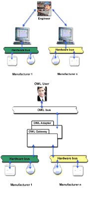
We introduce a layer of abstraction that is built on top of
the proprietary control systems which are hidden from the
users unless they need to see them, like a Luxmate engineer
that has to check Luxmate controlled facilities. Controlled
objects can form a group and be associated with commands
that change their settings. We call this a scene. Scenes can
be changed dynamically and belong to users. Users can adapt
their environment, starting with a default environment set
by a facility manager.
The
paper is organized as follows. In the
next section we represent
the requirements and models of an adaptable framework for
intelligent home/office applications, such as a facility
management system. In section "System
Design" we give an
overview of the framework, and in section 4-8, we describe
the system components. A major design goal was the use of
design patterns (see Gamma et al.,1996) to create a reusable
and extendable framework. For our models we use the Unified
Modeling Language from Booch et. al (1998). We describe the
status of our work in section "Prototype"
and related
work in the next section.
We conclude with a summary
and future work.
|
Requirements
Analysis
Scenarios
The
following set of scenarios represent typical use cases for a system
based on the OWL framework.
Scenario 1: Control.
Office worker Ralf enters his office. He launches the OWL based
facility management application, and changes the view appropriately
to display the floorplan of the office and the controls for all the
devices associated with it. He adjusts the lights for better comfort.
A moment later, the lights and the louvres in the room are set to a
new level that satisfies his preferences. The display warns him that
one lightbulb is inoperative. Ralf replaces it and the display
indicates that the lightbulb is working again.
Scenario 2: Directing
The
facility user Jane wants to make her office more comfortable. She
logs into the system, defines a new group of office facilities, and
assigns new settings and behaviors to them, such as starting the air
conditioning after she entered the office building, and closing the
louver of the upper windows. She saves this scene under the name
"Jane's summer settings", and attaches it to her user
profile.
Scenario 3: Getting Status
The
facility manager Joe takes inventory of the equipment in a particular
room. After launching the OWL based facility management system, a
display comes up with a view of the entire site. Joe selects the
appropriate building and views its 2-dimensional layout. He requests
"Show me conference room B," and a moment later the display shows the
room and its contents. The temperature sensor for the room shows that
the temperature is currently fluctuating between 76 and 77
degrees.
Scenario 4: Diagnosis
The
facility manager Jack receives an alarm on his personal digital
assistant indicating that an air-conditioner is malfunctioning in a
certain room. Visiting the room in 3-dimensional mode, the facility
manager selects the hot spot associated with the air-conditioner
which contains information such as model, make, last date of
maintenance, serial number, manufacturer and an error code for the
failure.
Scenario 5: Repair
As
the damage is only minor the facility manager orders the caretaker
Wilma to repair the malfunctioning air-conditioner. As the site is
quite large the caretaker uses a wearable computer with head mounted
display where she is shown the shortest way to the room. Vendor
specific on-line repair instructions have already been transmitted
together with the provision of the appropriate replacement part for
the air-conditioner. After Wilma repairs the air-conditioner, OWL
automatically reports to the facility manager that it has
successfully been restarted.
Functional Requirements
The
functional requirements for the OWL framework are:
- navigate
remotely through a corporate site at varying levels of
granularity, where a corporate site is defined as a set of one or
more globally distributed company sites.
- visualize
critical information such as ownership of workspaces, distribution
of resources such as computers, desks, calendars.
- dynamically
reconfigure building resources.
- control
sensors for the environment and climate such as light fixtures,
blinds, HVAC systems, heaters and thermostats.
- allow a
user to set up and run a simulation to compare different
architectural solutions.
- visualize
sensor information and the effects of controls.
- remotely
manage the facilities of a site that includes several distributed
buildings.
- allow a
user to define custom configurations for one or more facilities
and save them as a scene.
Non-functional Requirements
To
provide a truly usable application that competes with the simple
operation of a light switch, it is important to note, that users will
simply not accept a system that would require the operation of
lightswitches via a desktop computer. Turning on the lights of an
office should be as simple as using the light switch in that room.
This has important ramifications for the human computer interface of
applications using the OWL framework. First, the control system must
be accessible via standard light switch interfaces. Second, the user
interface must be provided with a meaningful display of the
information obtained from the system sensors, as well as a mechanism
that allows easy manipulation of sensors. The framework therefore
should support different types of inputs, for example speech-based
input, pen-based input, mouse/keyboard based input and other
modalities such as gesturing, clapping, face tracking, and motion
sensing. Moreover, the applications using the OWL framework should
not expect users to have their hands free when interacting with the
system. For security reasons the framework has to be able to safely
authenticate the user that wants to manipulate a device. Third, the
system must be platform independent, and interact with control
systems from different manufacturers. To provide manufacturer
independence, the OWL system has to be flexible and modular to
support hardware from different vendors with various degrees of
computer interaction and a variety of input/output controls. In
particular OWL must be able to simultaneously control a variety of
sensors provided by different manufacturers.
Finally, the OWL system must provide location transparent access to
sensors and actuators of the whole site, independent from their
physical location.
Structural Model
We
use several UML class diagrams to describe the structural model of
the OWL framework.
Section "Static model of a Site"
gives an overview of the framework.
Section "OWL User" and
section
"OWLObject" discuss the
abstractions OWLUser and OWLObject. Section
"OWL User" also describes how Scene
objects associate an OWL user with OWL objects.
Static
Model of a Site
|
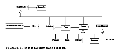
The static facility model is an
abstraction of corporate sites as they can be found in
reality. Examples for static models are CAD models created
by architects. The OWL static facility model is similar to
the SEMPER model (Mahdavi, 1996), and can be instantiated
with data from a CAD system such as MicroStation from
Bentley Systems (Bentley Systems, 1999). This model can be
used to display buildings in 2D or 3D. All objects of the
static facility model are tangible objects that exist in the
real world and have certain geometric attributes.
|
|
OWL
User
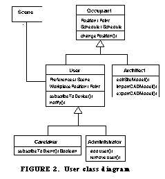
OWL distinguishes five types
of OWL users with different needs and rights.
Occupant
An Occupant represents
a person physically located in the site or building. An
Occupant has a location and a user profile. An Occupant may
move within the site, and change its position.
User
A User can control and
observe resources in the building. A User must be properly
identified and can have different access rights for
different resources. Users can specify a variable number of
user-specific preferences as scenes to customize their
environment, and have a specified workplace
position.
Administrator
Administrators
manipulate devices, manage users and groups, define a set of
predefined OWL events and formulate default settings for
user profiles. The Administrator can also define specific
access rights to rooms or devices. A synonym for
Administrator is facility manager.
Caretaker
Caretakers are
Users with the additional capability to receive OWL events
(
See Event Hierarchy. )
from devices. This could, for example, be events for damaged
light bulbs or events associated with the heating system.
Caretakers can also add new OWL events to the event
hierarchy.
Architect
Architects are
responsible for the static model of the building or site.
They have the right to import/export complete models from
CAD systems into a OWL bases application as well as modify
the models.
|
|
OWLObject
|
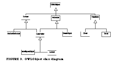
OWLObject is the super class of all objects that represent
any tangible object of the real world and that may be
contained in a scene. The subclass Sensor contains all
devices of the real world that are capable of generating
events, for example a motion sensor. Actuators are devices
that can react on commands, for example simple lightbulbs
are actuators. Controllers are able to do both. For example,
a lightbulb that "knows" its condition would be a
controller. Furniture is neither a sensor nor actuator
because it does not have a built-in controller that reacts
on electronic signals. Note that in our classification, a
simple Edison-type lightbulb is a Furniture object.
Furniture objects can be included in scenes, for example an
OWL scene might require a beamer for a slideshow
presentation. Inclusion of non-Controller objects is also
important to support mobile users who frequently change
their offices but require the same OWL scene to work
effectively in different parts of the building or at
different sites.
|
|
Scene
|
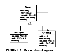
Scenes are an important feature of the OWL system and are
modeled with the composite pattern (Gamma et. al, 1996). An
OWL scene is either a single OWLObject or a Grouping object
that in turn may consist of several lower level OWL scenes.
The use of the composite pattern allows users to change a
scene dynamically. Scenes are linked to user profiles
allowing users to modify existing scenes or create their own
user-specific scenes.
Scenes allow users to provide OWLObjects with commands that
have to be executed. Scenes can subscribe to OWLEvents.
Assume, for example, a scene from user Jim that contains two
OWL objects Heater and Light. The scene includes commands
for starting the heating half an our before Jim enters his
office. When the timer device issues a timer event Jim's
scene checks the time, and orders its scenes to execute the
command to start up the heating device.
|
|
System Design
|
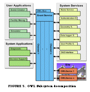
The OWL framework consists of four major subsystems, User
Applications, System Applications, System Services and OWL
Objects (see Figure 5).
User Applications are the Scene Creator, Facility Management
and the Simulator. The System Applications provide services
for more than one of the User Applications. Examples of
System Applications are Diagnostics and Decisions Support
systems. The System Services provide common services needed
by the User Applications as well as System Applications.
Systems Services are the Name Service, Authentication
Service, Geometry Service, Data logger Service and User
Profile Service. OWL Objects (see
See OWLObject. ) provide
access to the physical sensors, actuators and
controllers.
All the OWL subsystems communicate with each other via OWL
events using the OWL bus. Collection of OWL events can be
grouped into Channels. Any OWL subsystem is able to publish
and to subscribe to OWL events (see
See Event Hierarchy. ).
OWL users can also publish/subscribe to events.
|
|
OWL Bus
The
OWL bus supports two different types of communication among the OWL
subsystems: broadcast- and peer-to-peer communication. Broadcast
messages are sent by publishers to all the subscribers of a
particular OWL channel. An example of an OWL event publisher is a
lightbulb, which notifies a Caretaker of its current state as soon as
the Diagnostics System diagnoses a failure. There can be more than
one subscriber or more than one publisher to any channel.
The
OWL protocol provides a platform independent way for subsystems and
OWL objects to communicate with each other. It allows OWL objects to
discover each other, to receive a list of event channels that exist
for a given site, and to connect to the channels either as publisher
or subscriber. The OWL protocol also provides the ability to send
simple generic commands to other OWL objects. Once two OWL objects
have discovered each other, they can also communicate directly using
a specific protocol known only by the communication partners. For
example, the Facility Management application discovered some
lightbulbs, and receives references to them. Now it can use a device
specific protocol and invoke commands on those lightbulbs.
The
OWL protocol is realized by the Event Service, which is the backbone
of the OWL bus. The Event Service administers the event channels for
communication between OWL objects. Any OWL object using the OWL
protocol must connect to the Event Service. This is done with a
broadcast on a well-known channel that was established by the Event
Service. Once the OWL object is connected to the Event Service, it
can ask for information about existing event channels and connect to
any event channel either as publisher or subscriber.
Event Hierarchy
There are three types of OWL events. SensorEvents are emitted by
sensors somewhere within a site. SensorEvents allow OWL objects to
broadcast interesting occurrences such as a change in the temperature
or light, a motion, a vibration, smoke or something similar. The
second type of OWL events are Control Events that enable users and
OWL subsystems to send commands to other OWL objects. Simple examples
are "Start of OWLObject" and "Stop Operation of OWL Object". Response
Events allow OWL objects to respond to Control Events and user
actions such as turning on a light. Examples of Response Events are
"OWL Object has Started", "OWL Object has Stopped". OWL objects may
publish Response Events even if they did not receive the
corresponding Control Event.
OWL Families
|
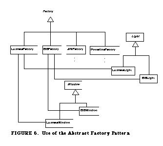
OWL objects from the same vendor specific control system are
modeled with the abstract factory pattern and the bridge
pattern (Gamma et. al 1995). All OWL objects from the same
vendor are grouped in a family created by the abstract
factory. In Figure 6, the European Installation Bus Family
(EIBFactory) creates a family of EIB controlled lights
(EIBLight) and windows (EIBWindows) whereas the Luxmate
factory does the same for Luxmate controlled devices
(LuxmateLight, LuxmateWindow). Using the abstract factory
pattern applications using the OWL framework do not have to
know how vendor specific lights are controlled. OWL based
applications simply access OWL objects, for example a light,
without knowing that it is a Luxmate controlled
light.
|
|
|
The bridge pattern shown in Figure 7 makes OWL independent
from vendor specific control systems. The functionality of
the OWL object Light, for example, is implemented by a
separate object, the LightImp Object, which connects to the
control system of the device. As the access to a control
system is vendor specific, subclasses of LightImpl are used
to do vendor specific tasks. For example, the OWL Object
Light for the EIB (EIBLight) is implemented by EIB which is
a subclass of LightImp.
|

|
User Applications
User
applications are predefined applications provided with the OWL
framework.
Facility Management
The
facility management application helps the facility manager to control
a building by providing him with different views of the site. For
example, one view might be a navigable map of all OWL objects,
another one might be a list of all malfunctioning
controllers.
Scene Creator
This
application allows the creation of user defined scenes. OWL presents
a list of the available OWL objects to the OWL user who can then
select some of them, group them, define a comfortable setting and
save it as a scene. Scenes can be attached to OWL events, so they can
be triggered automatically when the event occurs. An example would be
the start of the HVAC system and the closing of all the blinds in a
set of offices, when a certain temperature has been
reached.
Simulation
This
applications allows simulations to be run on a site or on a building.
Administrators are able to manipulate the site without affecting the
real environment. For debugging and testing purposes, they can
manually create OWL events.
System Applications
Decision Support
This
subsystem analyzes user behavior and generates models about the
behavior. That way inefficient behaviors (waste of energy) might be
detected by comparing the actual behavior with an optimal
model.
Diagnostics
The
diagnostics subsystem detects system failures and behaviors of
devices changing over time. For example the addition of new sensors
or actuators to the site might cause a change in the behavior of the
building such as an increase in energy use in a particular set of
offices.
System Services
Name Service
All
subsystem are location independent, therefore a mechanism for
locating the subsystem is necessary. The Name Service subsystem keeps
track of all systems. Each subsystem has to register with the Name
Service.
Authentication Service
This
service provides the possibility for the authentication of users. OWL
uses authentication for authorization checking of user commands such
as stopping the main server, and for applying the correct user
profile. Examples for authentication methods are fingerprint scanning
or an iButton from Dallas Semiconductor Corp (1999).
Datalogger Service
This
service logs OWL events when OWL based applications are running. For
example, the data can be used in field service applications for
error tracing as well as by the Diagnostics subsystem.
User Profile Service.
A
user profile stores a range of user specific information such as the
name of the user, and scenes associated with the user. User profiles
can be stored on a smart card or in a local database, accessible via
a local area network.
CADInterface
This
subsystem provides the interface and import/export filters for
different CAD formats and tools. The interfaces can be used for
dynamic updates of the building by importing updated CAD model of the
building or site.
Geometry Service
3
dimensional views of buildings cannot be generated on the fly without
any preprocessing, especially on devices with small compute power
like wearable devices. The Geometry Service connects to the
CADInterface and calculates a 3D model of the site or building. This
model can then be used by the user interface of a User Application to
provide, for example, a VRML model of the site.
Prototype
|
A conceptual prototype demonstrating some of the
capabilities of OWL has been developed for two distributed
locations: the Intelligent Workplace located at the Carnegie
Mellon University, and the Intelligent Home lab located at
the Technische Universität München. The prototype
provides access to two Luxmate lighting control systems via
a Web based user interface.
The prototype was developed with JDK 1.1. For the
implementation of the OWL bus we used remote method
invocations which we tested with CORBA 2.0 and RMI from
Javasoft, respectively. A comparison between the approaches
with CORBA and RMI can be found in Fernandes
(1997).
A
demonstration of scenario 1 is available on the OWL homepage
at http://atbruegge13.informatik.tu-muenchen.de/OWL. Two
movies show the scenario 1 "Control" where the OWL user Ralf
is working on his computer. One movie shows the user
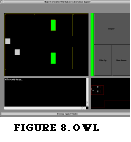
interface (see Figure 8) of the prototype, and the recording
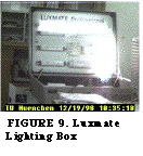
of the Luxmate lighting box (Figure 9) in parallel. The
second movie shows Ralf with his laptop in the lab. With his
OWL based facility management application he controls each
light of a Luxmate lighting system. The user interface shows
a detailed 2D floor plan of the OWL controlled building with
the lights symbolized as boxes in the upper left corner. The
upper right corner contains the control buttons for the
certain lightbulb that is actually selected. The lower left
corner contains control output, and the lower right corner
is for 2D navigation through the building. The movies show
how Ralf switches several lights on and off. When a light is
switched off the light icon is gray, when it is switched on
it changes to green. When a lightbulb is out of order
(demonstrated by Ralf removing the lightbulb) OWL announces
it to the user by turning the light icon red. OWL also knows
the location of the lightbulb from the CAD drawing, and
moves the focus of the detailed map to that location. When
Ralf replaces the lightbulb the light icon turns
green.
|
|
Related work
Control bus systems such as EIB or Luxmate are not designed for
openness and collaboration. They enable the control of building
facilities such as lightbulbs but do not incorporate any intelligence
into the devices. Instead the devices are controlled by a centralized
control unit.
Other approaches handle electronic devices as objects, and establish
communication between them. The objects are accessible over an object
oriented API. Examples are the JINI technology from Sun Microsystems
(see JINI homepage on Javasoft 1999) for Java capable devices,or the
HAVi homepage (1999) for Java capable home entertainment devices.
Another effort is the Open Service Gateway Initiative (OSGI, 1999)
that aims at specifying an open standard for connecting the coming
generation of smart consumer and small business appliances with
commercial Internet services on top of JINI. Related efforts are also
persued in the Things That Think consortium of the MIT Media Lab (see
the TTT homepage,1999), for example in the Personal Information
Architecture group (see PIA homepage, 1999), or the Hive project.
(see Hive homepage, 1999).
OWL
provides an object-oriented and open framework that integrates all
the objects available in a building and makes them available to
applications such as facility management. By using design patterns
OWL provides uniform access to all devices, independent from the
control system. Additionally the concept of "scenes" allows users of
OWL to personalize their environment.
Schulz and Schütze (1996) modeled a facility control system and
facility simulation with the casetool Statemate. This model could be
used for a refinement of the structural model used in OWL.
The
Adaptive House project of Mozer et al. (see Mozer, 1999) uses
neuronal networks to learn the users behavior. The goal is to
anticipate user needs and to conserve energy. The system is called
ACHE (AdaptiveControl of Home Environments), and uses low-voltage
conductors for collecting sensor data and a power-line communication
system for controlling lightings, fans, and electric outlets.
Applications like the Adaptive House could be built on top of the OWL
framework.
Summary and future Work
In
this paper we presented an object-oriented framework for a family of
collaborative building applications, such as distributed facility
management. First we developed the requirements for a facility
management system that is general enough to adapt to the needs of
different user types ranging from the facility manager to normal user
such as an office worker. With these requirements we designed a
framework that consists of subsystems communicating via the OWL bus.
We then described the subsystems in detail and showed where the use
of design patterns lead us to manufacturer independence and
reusability. Finally we described an existing conceptual prototype
and the relation to other research efforts.
We
continue to work on the OWL architecture in two directions. First, we
would like to improve the software architecture with respect to
building management. Our future efforts will aim at a stronger user
integration into OWL controlled environments. This includes several
aspects such as mobile users equipped with augmented reality systems,
various authentication methods, and agents for negotiations of
competing user needs.
Second, we would like to extend the OWL architecture to a general
purpose framework for a wider class of applications. We hypothesize
that applications such as train maintenance, aircraft inspection,
remote health care and car diagnostics can be addressed with an
architecture very similar to the one described in this paper. The
issue is how to design a reusable framework that observes, controls
and diagnoses the overall behavior of a sensor space. We are
currently in the process of generalizing the OWL framework for this
abstract problem (see Bruegge et al., 1997).
References
- Bentley
Systems (1999): MicroStation Academic Edition,
http://www.bentley.com/academic/products.
- G. Booch,
J. Rumbaugh, I. Jacobson (1998), The Unified Modeling Language
User Guide, Addison-Wesley.
- B. Bruegge,
B. Bennington. (1995). Applications of Mobile Computing and
Communication, IEEE Journal on Personal Communications, Special
Issue on Mobile Computing, pp. 64-71, February 1996.
- B. Bruegge,
T. Fenton, K. Tae Wook, R. Pravia, A. Sharma, B. Fernandes, S.
Chang, V. Hartkopf (1997): Turning lightbulbs into
Objects.
- Carnegie
Mellon Unversity (1996a): OWL I Homepage,
http://cascade1.se.cs.cmu.edu/15-413/default.html.
- Carnegie
Mellon University (1996b): The Intelligent Workplace,
http://www.arc.cmu.edu/cbpd/iw_press.htm.
- Carnegie
Mellon University (1997): OWL II Homepage,
http://cascade1.se.cs.cmu.edu/15-499/default.html.
- Dallas
Semiconductor Corp (1999): www.iButton.com,
http://www.ibutton.com.
- European
Installation Bus Association (1999): EIBA,
http://www.eiba.com.
- B.
Fernandes (1997). An Experimental Evaluation of A Component-Based
Distributed Application: The OWL System, Master's Thesis, Carnegie
Mellon University.
- E. Gamma,
R. Helm, R. Johnson, J. Vlissides (1996): Design Patterns,
Addison-Wesley.
- HAVi
Consortium (1999): HAVi - home, http://www.havi.org.
- Hive
project (1999): Hive - a TTT Toolkit,
http://hive.www.media.mit.edu/projects/hive.
- Javasoft
(1999): JINI Technology Architectural Overview (1999),
http://www.sun.com/jini/whitepapars/architecture.pdf.
- Johnson
Controls (1999): Metasys(R) Facility Management System,
http://www.johnsoncontrols.com/Metasys
- V.
Loftness, V. Hartkopf, A. Mahdavi, S. Lee, A. Aziz, and P. Mathew
(1994): "Environmental Consciousness in the Intelligent
Workplace," Paper presented at NEOCON 1994, held in Chicago,
Illinois, June, 1994.
- S. Schulz,
M. Schütze (1996): Modellierung einer Gebäudesteuerung
und -simulation mit Statemate, 4. Deutsches Anwenderforum für
STATEMATE/ExpressV-HDL, Systemtechnik Berner & Mattner GmbH,
Munich (D), June 1996.
- TTT (1999):
Things That Think, http://www.media.mit.edu/ttt.
- A. Mahdavi
(1996): SEMPER: A New Computational Environment for
Simulation-based Building Design Assistance. Proceedings of the
1996 International Symposium of CIB W67 (Energy and Mass Flows in
the Life Cycle of Buildings).Vienna, Austria. pp. 467 -
472.
- R. Maxion,
R. Olszewski (1998): Improving Software Robustness with
Dependability Cases, The Twenty-Eighth International Symposium on
Fault-Tolerant Computing, pages 346-355. IEEE Computer Society
Press.
- Mozer, M.
C. (1999): An intelligent environment must be adaptive, IEEE
Intelligent Systems, in press.
- MIT
PIA-Group (1999): Personal Information Architecture Group - PIA,
http://www.media.mit.edu/pia/index.html.
- OSGI
Consortium (1999): OSGI Homepage,
http://www.osgi.org/osgi_html/osgi.html.
- Zumtobel AG
(1999): Zumtobel STAFF The Light,
http://www.zumtobelstaff.co.at/luxmate.
This page is hosted by the Chair for Applied Software Engineering of the Technische Universität München.
Imprint (Impressum)


