 |
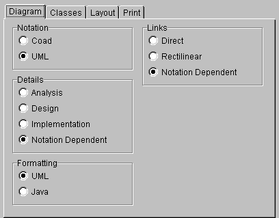
| Figure 1. Diagram tab |
| Together User Reference: |
| Dialogs
Reference |
Options dialog |
| DIAGRAM TAB CLASSES TAB LAYOUT TAB PRINT TAB CODE EDITOR TAB TOOLS TAB | |
|
|
|
Notation
Coad - analysis |
Formatting
Attributes... name : type
Attributes... type name
Coad - Rectilinear |
|
| Figure 1. Diagram tab |
| Initial Maximum
These values determine the maximum width and height of a class when a diagram is initially created. When a classname (which may have a leading package name) is shortened it is displayed right aligned with three leading dots. Classes can be manually resized later.
|
Subpackages
(This option only appears if the product version you have supports Java) |
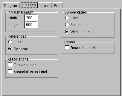 |
| Figure 2. Classes tab |
Inheritance
Bottom - classes placed horizontally in the same row are aligned to bottom of this row |
Quality
High (default) |
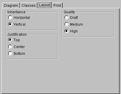 |
| Figure 3. Layout tab |
| Here you can setup the page size, orientation,
margins and options.
Paper size
|
Options
|
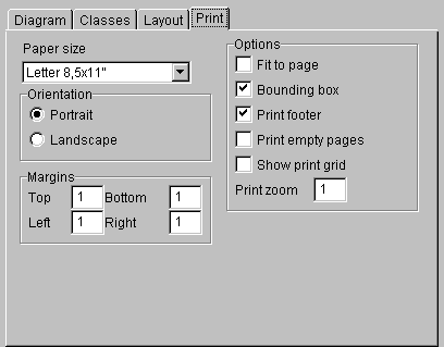 |
| Figure 4. Print tab |
| Confirm delete:
Optionally display confirmation dialog when physically deleting a class, package or diagram. Delete confirmation is enabled for all elements by default.
|
| Collection Blueprints:
Select which sets of collections (containers) to include in the Choose Pattern dialog. The default configuration file contains 4 sets of blueprints for creating links implemented as collections for various libraries. Check those collections you work with. This enables to decrease the list of patterns in the Choose Pattern dialog. This version of Together has the following collections:
|
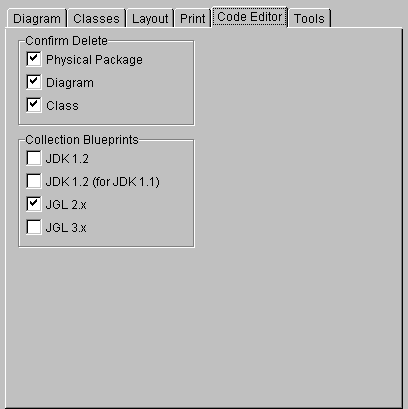 |
| Figure 5. Code Editor tab |
Note: This tab only displays when the Options dialog is invoked
with Edit | Global Options. It is not present when the dialog is called
from the Diagram context menu.
| Tool launch command(s) for:
A drop-down list of elements that have context menus on which you can create additional commands that launch other applications. Selections:
|
|
| Current command(s):
The list of Tools (i.e. other applications) currently established on the context menu of the item selected in Tool launch command(s) for. The order of commands in the list matches one in the context menu. |
Add:
Add to the list of tools that the element in Tool launch command(s) for launches. Remove:
Move Up:
Move Down:
|
| Label for context menu:
You can rename here the command selected in the Tools list. This name also appears on the context menu of the item selected in Tool launch command(s) for. Command:
Parameter(s):
|
|
| Apply output management:
Some console tools (especially batch or command files) can't be started directly. Together provides a special OS-dependent output management tool oistart that starts such programs correctly. It also catches program output and writes that to a file. (Note: this option appears in some builds as "Use oistart") |
Caution: Checking this option is
necessary for reliable tool output under Windows. When you uncheck it,
a warning message displays.
You can disable this message by specifying options.tools.warning.disable_oistart = no in config.properties. |
| Wait and Update:
Diagrams are updated after the tool operation is complete. Enabled only if Use oistart is checked. |
Caution: External tools can perform modifications of the source code (e.g., revision control commands). Checking this option makes you free from manual invoking Update All diagrams. |
| Console Tool:
Specifies that the Tool is a console application and its output is redirected to the Message Log window (see Getting Started: About the Main window). Enabled only if Use oistart is checked. |
Caution: This option should be
used with care - if a tool waits for user input or if it is a GUI application
(Windows, PM, Motif, etc.) the option should not be checked. If
it is, the tool waits but you can't see the prompt so it seems like the
tool hangs.
Also note that some console applications may use a non-standard output device. In this case, the output can't be captured to the Message log. |
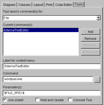 |
| Figure 6. Tools tab |
The external tools feature enables you to integarate with a version control system (VCS) such as MS Visual Source Safe or PVCS. By setting up appropriate tools commands, you can configure Together to interact with a VCS to create projects, add or delete files, check files and directories in or out, etc.TOPTogether provides two sets of batch files to help you quickly set up commands for either MS Visial Source Safe (vss*.bat) or PVCS (pvcs*.bat). These files are installed to the bin directory.
To set up VCS interaction, you can call these batch files on the Command line, passing appropriate macros, described above, as paramaters .
See the readme_vss.txt or readme_pvcs.txt file in the bin directory for info on order of parameters.If you use a VCS other than MS Visual Source Safe or PVCS, you can use the files supplied with Together as a starting point and edit them as needed to adapt to your VCS.
| GO TO TOP | USER REFERENCE | USER GUIDE | GETTING STARTED | HELP CONTENTS |